General Mounting Instructions.
You need to use this instruction only if there is no specific
instruction for Your particular machine.
This instruction takes only a few minutes longer than a specific one,
and will provide a 100% safe and top performing LClock upgrade.
Getting started !
- Check for your CD Player in the CD Player Clock Freqency Table below :-
| Make / Model | Clock Frequency (MHz) |
| Accuphase DP90 | 16.9344 |
| Arcam Alpha 5 plus | 11.2896 |
| Cambridge CD6 | 11.2896 |
| Cambridge Discmagic | 16.9344 |
| Denon DCD725 | 16.9344 |
| Denon DCD1500 | 8.4672 |
| Denon DCD3300 | 16.9344 |
| Denon DCD3560 | 16.9344 |
| HOLFI Xara | 16.9344 |
| HOLFI Xara SE | 16.9344 |
| Kenwood DP7030 | 45.1584 |
| Kenwood DP7060 | 16.9344 |
| Kenwood DP7090 | 16.9344 |
| Kenwood L-1000D | 67.7376 |
| Marantz CD 52 | 11.2896 |
| Marantz CD 63 SE | 16.9344 |
| Micro Mega Leader | 11.2896 |
| Micro Mega Stage 1..2..3 | 33.8688 |
| Parasound C/DP 1000 | 16.9344 |
| Pink Triangle Numeral | 33.8688 |
| Pioneer PD75 | 16.9344 |
| Pioneer PD95 | 16.9344 |
| Pioneer PDR-04 | 16.9344 |
| Pioneer PDS 505 | 16.9344 |
| Proceed PCD-2 | 11.2896 |
| Rega Planet | 16.9344 |
| Rotel RCD-965 BX | 11.2896 |
| Rotel RCD-970 BX | 11.2896 |
| Rotel RCD-971 | 16.9344 |
| Rotel RCD-975 | 11.2896 |
| Rotel RH-CD10 | 16.9344 |
| SONY CDP-497 | 22.5792 |
| SONY CDP-555 ES | 16.9344 |
| SONY CDP-X7 ESD | 16.9344 |
| SONY CDP-X222 ES | 45.1584 |
| SONY CDP-X229 ES | 45.1584 |
| SONY CDP-X777 ES | 45.1584 |
| SONY CDP-X779 ES | 45.1584 |
| SONY CDP-XA-5 ES | 45.1584 |
| SONY CDP-XA-7 ES | 45.1584 |
| SONY CDP-XB920 | 45.1584 |
| SONY CDP-XE900 | 45.1584 |
| Teac VRDS-10 | 16.9344 |
| Teac VRDS-T1 | 16.9344 |
| Technics SL-PS620A | 33.8688 |
| Technics SL-PS840 | 33.8688 |
| Thule CD-100 | 11.2896 |
| Thule Spirit | 16.9344 |
- Take the top cover off Your machine, by removing screws in the side and/or top and back of the enclosure.
- Locate the Crystal unit, it's a shiny metal surface component on the PC board, mostly the right hand side, when you view the CD from the front panel. The size of the crystal unit is 10 by 15 mm. or 1/2 by 3/4 inch. It may be encapsulated in a black rubber housing, or textile tape.
- The Crystal unit has a frequency marking, we need in order to send you the right LClock unit.
- Here are the options for this marking:
| 8.4672 |
| 11.2896 |
| 16.9344 |
| 22.5792 |
| 33.8688 |
| 45.1584 |
- The marking may only consist of some of these numbers. for instance 45.15 is normal for a 45.1584 MHz unit. Something like 169NDK is not unlikely for a 16.9344 MHz unit.
1..Remove the crystal unit in Your CD player. To do this You may have to unmount a PC board, and/or unplug some wire connectors. Be sure to draw a sketch of where each wire connector fits in again, or check if they can only go in one way, as in most players.
2..Remove two capacitors placed right next to the crystal unit, they are marked with something like: 10, 12, 15, 100 or 1000. These two parts are placed within a 2 cm / 1" range of the crystal, They have a printed number on the PC Board, starting with C, i.e. C102. You can't mistake them for anything else.
3..The point on the PC board, where the two capacitors You just removed, connect together, is the GND. Connect LClock GND to this point. GND is clearly marked on the LClock unit.
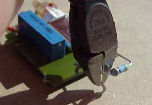
4..A 500 Ohm resistor is connected from Out to Gnd on the LClock You have. Cut the Gnd side of this resistor leaving only 3-4 mm. wire on the resistor. Connect the free end of the resistor to any of the two solderpads where the crystal unit was just unsoldered from the CD player PCB.
 -
-
5..Connect LClock's red wire to a 12V power supply. Most machines have
an 7812 voltage regulator in them, connect the red wire to the right hand
(output) pin, when viewing the '7812' text correctly. An 7805 can also
be used to connect the red wire, but in this case, use the left hand (input)
pin, when viewing the '7805' text right. LClock has it's own on board precision
voltage regulator. Therefore any voltage between 8 and 20 Volts is appropriate
for running the unit. You could just use a multimeter to locate a power
source for LClock, (Draws 10-12 mA DC).
 |
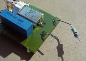
Connecting the 7805/7812... | ...The LClock unit. Gnd and Out is clearly marked on the PCB. |  |
7..When the machine seems to be in working order, remove the 500 Ohm resistor, and connect the LClock Out directly to the right crystal solder pad. (Where the CD player was functioning correctly).
8..Fit screws and connector wires back in, put a CD in and check the CD player by listening to some well known music.
9..Adjust the (20 turn) trimmer on LClock, turn it a few revs counterclockwise, and then twice as many revs clockwise. If no loud noise is heard, just turn it back to a position in between, and leave it. Else find an interval on the trimmer where the sound is clean, and does not break up. Set the trimmer in the middle of the usable interval.
10..There is no sonic performance gain in setting the trimmer to a precise position. If it works it works perfectly.
11..Put Your machine back together, the optimal performance will occur after approximately 48 hours with power on the CD player, (no need to play all the time).